REFURBISHING THE NAUTILUS MINISUB
~ PAGE FOUR ~
SCROLL DOWN FOR LATEST
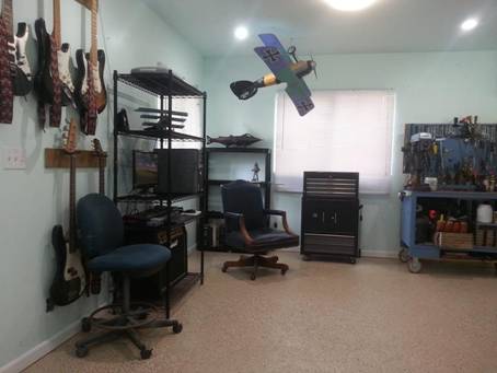
It's taken a long time and a lot
of hard work in my spare time to reach this point, but the shop and storage are
finally set up and work on the Nautilus Minisub is
underway again. This is my new office.

Wearing it's
rotary collar, the dusty sub rides on a wheeled carrier in the shop.


We've obtained the
shafts, bearings, seals, couplers, through-hull, and propeller shaft for the drivetrain.

Guidance control
will be achieved via medical-grade 12-volt actuators to move the rudder and
planes.

As of September 17th, 2018, I've purchased this 48 volt motor and controller
system (with potentiometer instead of a twist grip) rated at 6 hp continuous
and 16 hp for sprints of up to one minute.
I could have gone bigger and more powerful (and still can if I later
want to change the motor and controller)
but I don't believe we'll need it.
If this boat cruises in the neighborhood of 5 to 6 mph and can sprint
briefly at a top speed of, say, 10 to 12 mph; that will be about right for
performance, appearance, and spectator appeal.
And even by conservative calculations, this system should be able to
spin a 10" diameter by 10"
pitch propeller fast enough to do that and maybe more.

So, with all the major
components for the drivetrain and control system
upgrades either on our shelves or in the mail, here's the plan. (1) Assemble and water-tank test the
propulsion system and bench-test the guidance actuators. (2) Install them in the submarine using the
original through-hull stuffing boxes and shafts; repacked, of course. (3) Install all previously-removed exterior
metal plating so she looks exactly like she did during the proving tests of
1991. (4) Check and dry-test weight
& balance and adjust component (battery) position as necessary to achieve
normal CG with pilot weight in the cockpit.
(5) Launch the boat and conduct surfaced and submerged tests of the new
propulsion and guidance systems. (6)
Modify the hatch, foredeck and pilot house for lighter weight and greater ease
of access. (7) Replace the control
through-hulls with pressure-compensated units containing bearings, seals, and
packing on lathe-turned stainless steel shafts.

After the boat is running
properly, I'll "put the icing on the cake" with
exterior detailing as seen in 20,000
Leagues Under the Sea. Rakers, headlights, gills, hatches, skiff, anchors,
fairings, and about 15,000 simulated rivet heads. All that good stuff. J

Tuesday, September 18, 2018: These
are the basic components for the propeller shaft. Two pillow blocks support a stainless shaft
with couplers; one mates to the motor and the other to the stuffing box. My only concern is that this shaft has a key
slot cut from end to end and I'm wondering what that variance in weight might
do when it's rotating at high speed.
Might have to swap this for a better shaft. I'll see what kind of vibration we get when
there's a motor turning it and decide then if it needs to be replaced. If not; this is what we'll be running.

Here it is lined up to measure
the length. For the first tests I'll
leave the end of the shaft from the JS-550 as is and turn a squirt drive in the
test tank because (1) that will be easiest and (2) we already have the squirt
drive. All I need to do is put a
hydrostatic load on the motor. The
JS-550 stuffing box contains bearings and seals and is watertight at moderate
depths. But after the shaft leaves the
pressure hull, it will also pass through a short pressure-compensated
bearing-and-seal case that I'll have to make.
That will ensure no water even gets to the stuffing box, let alone
inside it. So the already slim chances
of a propshaft leak into the pressure hull are
greatly diminished. When the tank
testing is done and we have to go to a propeller for the submarine, cutting
this shaft off at the start of the taper will give us the perfect length to put
a prop where it should be in the tail section.

Here's the JS-550 outbox, shaft,
and pump we'll be using for the first load tests of the motor. All newly rebuilt and ready go. The water-testing tank will get a hole in the
side that the stuffing box bolts onto.
Inside the tank, the pump will be securely bolted to a 2X6 screwed to
the tank walls, thus keeping the pump submerged. A big, heavy, glass table top will cover the
testing tank and we expect to see some real action in there!

The stuffing box is watertight
but again; I'm backing it up with an externally-mounted pressure-compensated
bearing case so water shouldn't even touch the box's aft end. Another important function this unit performs
is to act like a thrust bearing. Electric motors like mine aren't made to take
the axial loads usually imparted by a propeller so some kind of thrust bearing
is necessary to absorb that shock. In
this case, the stuffing box is bolted to the hull and will serve as a very
excellent thrust bearing.

Also today, we got a look at our
new gas analyzer that will be monitoring CO2 levels in the passenger compartment. Above that are the position indicators and
sensors we have for the rudder and dive planes.

Saturday, September 22, 2018:
The linear actuators arrived and have bench tested OK. They are slower than I thought, though. I can use them to operate remote valves in
the tailcone but for the controls I've decided to go
with power window motors and regulators.
The battery bears witness to how dusty it got in the shop before we did
the Epoxyshield floor. Nice and clean down there, now. J

Also today, we added a
controller heat sink and the Sevcon Clearview display to our motor order. The heatsink
protects the controller and this readout provides necessary information if we
want to alter the performance parameters of the motor. It will also come in handy when doing the
wet-tank tests of the drivetrain to determine RPM
under load and help us decide on the proper pitch for the propeller. Not inexpensive, but invaluable to the
project so it had to be.

The company I bought my shaft
couplers from only had SAE. The shaft is
M18 X 1.5 so I adapted an SAE coupler to Metric. There's a rubber "spider" between
couplers to absorb some shock. The only
problem here is, this shaft is threaded to work with a squirt-drive that turns
counter-clockwise and the Disney Nautilus prop turns standard. So after we finish the first tank-tests using
the hydrojet, I'll have to modify it for a right hand
propeller.The couplers come with four threaded
apertures with allen-type set screws. I'll chuck it up on the drill press, drill
through the coupler and shaft, and install a stainless pin as used in "pin
drive" outboards; an easy fix that solves a serious coupler-mating
problem.

And just for grins, I've decided
to make the battery box and aft system control panel look like the ElectroVulcanic Generator described in my novel, VULCANIUM
(The Secret of Captain Nemo and the Nautilus.) I recently learned there's a cool little
plasma sphere device that, when combined with a battery box built like the
first EVG mentioned in the book, will provide an interesting visual effect when
the boat is on display. So tonight I
bought one plus a USB battery pack to power it.
If none of this makes sense, read the book; available at Amazon and
Barns & Noble. (Shameless plug.)
https://www.amazon.com/dp/1478700009

My houseguest, Blackie La Goon,
has been crashing in the Vette and is openly opposed
to me working on it. No problemo, Blackie!
I'm focused on the submarine at this time, so it's all good. Won't be long before you're gonna have to find a new place to sleep, though. And stop playing the stereo so loud at night,
will ya? Sheesh! J

Monday, September 24, 2018: CONTROL
ACTUATORS: The linear actuators are out!
Too slow! Now, to actuate the
rudder and diveplane outshafts
and bellcranks, I've decided to use three of these
power window motor / regulator units from a Chevy truck. I'll cut the section bordered in red away
from the unnecessary metal; put a slot in the regulator blade where a ball-pin
on the outshaft bellcrank
will ride. Energizing the motor /
regulator will move the bellcrank, outshaft, external bellcranks and connecting rods of the control surfaces
themselves. Individual actuators on the
dive planes allows for pitch and / or roll control via a four-way joystick
switch.

I began the design work that
lead to the Nautilus Minisub in the mid-1980's. I have always done my R&D with drawings
like this. No CAD. This is all the visualization I need to know
it will work. I save the detailed
drawings until I'm making the actual part.
Many guys I've seen online live to create and share pretty computer
pictures of things they dream of building, and oftentimes that's as far as they
ever get. (I call that"Analysis paralysis.") I'm the
polar opposite of that. I develop the
design in my mind by actually thinking about it, rough sketch it on paper, and
build it out of steel. No time or need
for anything else.
Saturday, September 29, 2018:
CONTROL ACTUATORS: The power window motors work nicely! Perfect speed and plenty of torque. Checking the clearances in the tailcone near the propshaft
through-hull, existing plumbing for the ballast tanks, and the location of the
rudder through-hull packing gland; I might have to use a linkage (like the
drawing above) for the rudder.
For the dive planes, I can turn
that black regulator piece into the inner bellcrank
by replacing the round pivot hinge with a square hole to fit the end of the
dive plane through-hull shaft. That will
apply torque directly to the outshaft without any
additional bellcranks or linkages inside the
hull. Simpler is betterer. J

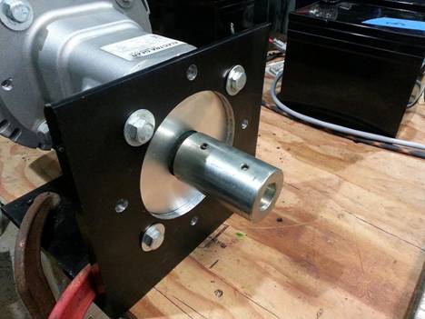
Wednesday, October 03, 2018:
PROPSHAFT: Been working on the drivetrain,
minus the motor. Looking into mounting
the motor as far aft as possible and measuring how that placement might
conflict with the existing ballast plumbing and proposed electric guidance
control mechanisms. Also seeing how that
affects weight and balance. So far, it
looks doable.

In this pic,
I am checking the positioning of the JS-550 propshaft
and gear box inside the tailcone where they will
eventually be bolted to the end cap.
There will be a bearing supporting the shaft at the end of that
wrap-around cylindrical motor mount where the original Minn
Kota trolling motor once resided. After
we've done the hydrostatic loading tests of the motor using a jetski squirt-drive; I'll cut the shaft off at the start of
the taper, put a 1/4" keyway in it and thread the end for a pin-drive
propeller and nut.

ELECTRIC COMPASS, CLOCK, AND
TEMP GAUGE: When I bought this
inexpensive electric compass, I had my doubts about it working inside an
all-steel double-hulled submarine and figured I could always put it in my
truck. BUT IT WORKS FINE! Accurate compass readings inside the
submarine and inside the shop to boot!
Didn't have this back in '91.
Sure will be nice to be able to actually navigate for a change. J

SALON WINDOW FAIRINGS: Years
ago, I began making and assembling the paper templates for copper pieces that
would comprise the salon window fairings.
Today, I'm getting ready to strip a lot of the exterior sheet metal so I
can perform major surgery on the pressure hull, but I don't want to lose what
I've done for the windows so far. So I'm
going to replace the lost (lower) paper templates and seal the shape with sheer
fiberglass cloth and resin. I might even
go as far as using Bondo to refine the shapes and
then glue on the cabochons as simulated rivet heads. When it's done I will build a box-frame
around it and pour rubber mold-making compound into it. That way, I will have a mold for making
fiberglass salon window fairings in 1:10th scale; lamp bezel, panel lines,
rivets and all. I decided long ago not
to make these out of copper because
insulating them from the steel (to avoid electrolysis in sea water) will
be very difficult to almost impossible.
I'll be using fiberglass and resin castings to detail other parts of the
exterior, so why not make the fairings out of the same stuff? No reason.
And I'll cast an extra to make a wall clock out of, too. J
Friday, October 12, 2018: THE MOTOR HAS ARRIVED! This is the ME1117 motor and Sevcon controller system I'll be running. 48 volts equals 6 HP continuous and 19 HP for
"full collision speed." Next,
I will assemble a battery pack and mount the entire drivetrain
on a test bench.

Tuesday, November 06, 2018: We now have the four propellers we'll test the drivetrain with.
We've covered a wide range of suitable diameters and pitches and will
check how the motor responds to each.
I'm pretty sure we're going to want a gear reduction box but first we'll
test these direct drive.
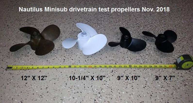
ALSO: I am building my own
5-bladed "Hammerhead" propeller (ala the Disney Nautilus) out of
steel. It will be functional but the
design isn't very efficient so it will mostly be for looks. When we want performace,
we'll be using something like what you see above.
Sunday, December 02, 2018: This morning I ordered a 2:1 GEAR REDUCTION for
the drivetrain.
Now, with the motor turning at a comfortable high end of about 4,000
RPM, figuring a 2:1 reduction and a 30% slip on the 12 X 12 prop, the
calculated boat speed is 15.9 MPH. In a
submarine of this size, type, and purpose; that should be plenty fast enough.

And this evening I made the
bushing that will adapt the splined end of our metric
JS-550 drive shaft to the SAE bore of our 12 X 12" four-bladed Michigan Wheel bronze propeller. I have the parts to adapt a shortened shaft
via a series of reducer couplings, but that's more complexity and weight and I
really don't want to have to cut this shaft if I don't absolutely have to.
The bushing is ground to the
proper ID and OD, and the ID flares to conform with the gradual shaft
expansion; making for a seamless transition without a "lip" or "
gap" where the coupler stops and the propshaft
begins.
With the prop and coupler
installed as seen in this picture, the propeller is staunchly attached and
true: zero play or wobble. It's a
"pin-drive" propeller so I'll drill the shaft to receive pins fore
and aft. Eventually I'll trim the end
of the shaft flush with the prop and install a hemispherical cap as seen on the
Disney Nautilus.

Mating the SAE propeller to the
Metric driveshaft was the last major engineering / fabricating obstacle to a
functional drivetrain. All I need now is the hardware to bolt
everything to an 8' 2X10 and then we're ready to start testing on the bench and
in the water tank.
Tuesday, January 29, 2019: Getting
the batteries shipped to Hawaii was a problem; getting them shipped via USPS undamaged
even moreso.
Of the four batteries I received one with a bent positive lug and
another with a cracked case, leaking acid.
Fortunately, the company will pay for return shipping and replace them
but going USPS is chancy.

Yesterday I assembled the 48V
battery pack and bench-tested the motor for the first time. Everything works as expected.

Key Switch; Forward/Reverse Switch; Potentiometer; Servcon display; Battery Pack; Motor; Controller &
Harness; Kill Switch.

Operating unloaded motor at about 2,500 RPM. Not going to wind it out first time
through! J

Servcon display shows motor pulling 6 A @
49.8 V to generate about 3,200 RPM in Forward gear. Hour
meter still reads Zero; less than 1 minute.
Next, I'll direct-drive the
JS-550 bearing box and propshaft to spin the propeller
on the bench. Here I'm almost done
trimming the bearing box mounting plate and I'm blocking up the propeller
bearing with scrap lumber to get the shaft at the right height and level.

Propeller; Bearing; Prop shaft; JS-550 bearing box & coupler;
bearing box mounting plate; motor.

Bearing box mount made and installed; drivetrain
set up for bench test. Runs fine.

Turns the propshaft no sweat! Next, I make the tailcone
pressure-compensated shaft housing and frame mounts out of steel.
Wednesday, February 06, 2019:
One of the batteries had a crack in the case and was leaking acid. I sent CHROME BATTERY a few pics and the replacement battery is in the mail at this
time.

I was ready to buy a gear
reducer last October when an EMS engineer advised me to wait as they were
switching manufacturers in 2019. Today,
I'm glad I waited. The new gear reducers
are available as of day before yesterday; mine is bought and paid for and I'm
awaiting delivery with the understanding that there might be a manufacturer's
lag of seven days or so. The ones
available last year were from China and featured a cast iron case. These new ones are made in the USA, have
helical gears, and the case is aluminum.

And yesterday I welded the propshaft tube to the bearing box flange and set it up with
bearings fore and aft. Shaft turns
easily and smooth. The bearing box is
rated for 6,000 rpm and is said to be waterproof to one additional atmosphere
but I'm not relying on that. The propshaft tube will be PRESSURE COMPENSATED to keep water from reaching the bearing box
in the first place; a little insurance against water leakage at the propshaft
through-hull.

Saturday, February 09, 2019:
Propeller, shaft, compensated
housing, and watertight bearing box looking good so far.

Here's the tailcone
bulkhead I made 18 years ago; adapted to attach with bolts and a gasket to the
drilled-and-tapped tailcone boss. Waiting to put the center aperture (for the
tube) in it until the gear reducer arrives and direct measurements can be
made. At least a week there.

Found a 1/2" variance
between "level" on the port and starboard dive plane outshafts. Doesn't
affect hull or control symmetry but it's not right, either. So I've been rethinking the rudder and dive
plane through-hulls and decided to rebuild all three with bearings, seals, and
pressure compensation rather than the homemade packing-glands we dived
(successfully) back in 1991.
Also, we've always had problems
with the hatch design and placement. In
1991, it was heavy, loosely-hinged, and stood upright aft of the CG. The pilot had to drop into the aft
passenger's compartment, slide forward under the deck support, and pop up into
the cockpit. Not ergonomic at all.
For a long time I've worked on
designs where the wheelhouse section opens like a knight's visor; straight up
either forward or aft. But again,
putting that much weight that far off the CG and above the longitudinal
centerline just screams "instability!"
The answer? I'm building it to slide aft; something like
the canopy of an F-86 fighter jet aircraft.
(Not exactly like this; but similar.)
The section of cabin and wheelhouse over and around the pilot will slide
up and back over the "gills" without standing upright like a
sail. That should work well and look
pretty cool, too.

And for those who look for
faults: yes, I know it's rusty!
Construction of the NAUTILUS MINISUB began in 1985, she was proven in
1991, and has been sitting in storage ever since. This boat is all steel and going on 30 years
old. Submarines rust; that's a fact of
life. So this project is the restoration
of a vintage homebuilt submarine as much as anything else. Fortunately, there are such things as
sandblasters. J
Saturday, February 16, 2019: Still waiting on the gear reducer. Meanwhile, CHROME BATTERY replaced one unit
that was leaking acid; no problems. A
good company to deal with and I'll be using them again.
Received and bench-checked one
of two 12-volt actuated valves; it works fine.
A shipping error delayed the second valve; presently en route.
Also, decided to go with genuine
HARLEY DAVIDSON axles and bearings for my rudder and diveplane
through-hulls. My original shafts are
3/4" stainless and still look useable but I want to make three new boxes
from scratch. Harley axles and bearings
are also 3/4" and matched to closer tolerances than I'd get using my old
3/4" rudder shaft. Toss in a couple
seals, pressure-compensate the housing, and there ya
go.

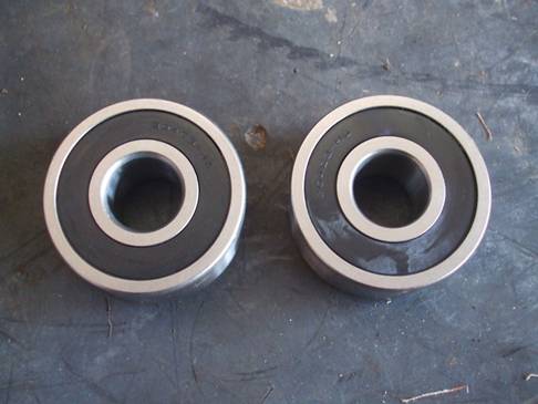
New reproduction 1966 Harley Davidson heel bearings.
Also, I've decided on 12-volt
linear actuators for the rudders and diveplanes. Simple installation; zero adjustments or
maintenance; quiet and powerful; fast enough for the task depending on how it's
linked to the output shaft. The power
window motors would have worked but they are bulkier and space is at a premium
in the motor compartment. Of the two
choices, this turns out to be the best way to go.

Tuesday, February 26, 2019: Received the 2:1 gear reducer last night. Here's a pic of the
drivetrain with main components laid out in reference
to each other but not operational yet.
Looks like everything is going to fit into the hull. I've some small details to attend to and then
we will be bench-testing the drivetrain. Almost time to cut the hull and install this
into the submarine. J

Tuesday, March 12, 2019: Been acquiring parts and steel for the project. (More about that on The Clipboard page.
) Have made the decision to make riveted
panels (for the exterior detailing) out of 3/32" acrylic sheet with
hemispherical acrylic cabochons bonded on with Weld-On Acrylic Solvent ™.
Just did a test. Glued two 5mm
cabochons together to make a sphere.
Also glued one cabochon to a scrap of acrylic. The chem-welded
bond is very fast; gives you a chance to change your mind but sets with a
powerful grip in only moments.
Manufacturer's specs say in 18 hours the bond should be able to
withstand 2200 psi sheering force. The
acrylic sphere and test piece I made about an hour ago are so solid, I am
exerting all the force I can with my fingers and thumb yet can't break the bond
apart. And it's not even fully cured yet! Fantastic!
No more worries about rivet heads coming off in the water! This is a tremendous improvement over even
the best of adhesives we've tested so far.
Acrylic on acrylic with acrylic solvent is the way I will do the
exterior detailing on the Nautilus Minisub.

5mm acrylic cabochons; two chemically fused together as a sphere
and one bonded onto flat acrylic sheet with WELD ON acrylic solvent.
Tuesday, March 19, 2019: PROBLEM. Ran the drivetrain
on the bench as you see it in the picture below. Got an unpleasant surprise!
I ordered the motor so it would
spin the propeller clockwise, as the Disney Nautilus does. Then I ordered the gear reduction. At no point did anyone or anything advise me
that the gear reducer would make the shaft turn opposite the motor.
In my case it won't affect
performance because the motor is set to provide the same power output in
forward or reverse. But the indications
on the Sevcon display will be backwards: R when we're
going Forward and vice-versa. Not happy
about that at all. I don't see how a
company that provides electric motor components for vehicles can make a mistake
that blatant. But there it is. I'll deal with it.

Also, I don't really like the
jaw-type shaft couplers; too sloppy.
Seriously considering revamping
the drivetrain with a solid 7/8" to 1-1/8"
one-piece shaft adapter / coupler and 1-1/8" stainless shaft all the way
to the propeller. That will eliminate
the JS-550 bearing box and shaft; relying solely on the bearings and seals
within the pressure-compensated propshaft housing,
which I'll handcraft.
On the upside, this will
eliminate the friction of the JS-550 bearing box and allow me to change the
length of the propeller shaft to move the motor further forward toward the
center of gravity. That's a good thing
for this particular application.
Lemons and lemonade. J
Wednesday, March 20, 2019: PROBLEM SOLVED. This 7/8" stainless steel shaft
coupling is keyed 3/16" and mates perfectly with the output shaft of the
gear reducer. I'm obtaining a 36"
piece of 4140 chrome molly TGP stainless steel shafting; will cut keyway slots
in both ends and thread the last inch of one end 7/8" X 16 tpi. The shaft will
then mate perfectly with this coupling.
Stainless steel shaft coupling.
The threaded end of the shaft
will fit into this vintage 7/8" keyed, straight-bore brass propeller;
measuring 12" diameter and 13" pitch.
It will be secured with a shaft collar forward and a castellated
7/8" x 16 TPI nut, washer, and cotter pin aft. It's a three-blade; not a four like we had
before or a five like the Disney Nautilus has; but this should actually give
better performance than the one we had before and I'll deal with the cosmetic
issues of making a 5-bladed hammerhead prop after the boat's running. But even then; I expect the performance to be
miserable and will only use it for display.
For now, we'll be running this three-bladed prop.

12 X 13 brass propeller with 7/8" bore.
I've eliminated the JS-550 bearing
box and shaft. The pressure-compensated propshaft housing will be adapted to receive 7/8"
bearings and seals. Getting the new drivetrain running is only a matter of receiving the
materials and getting the keyways cut.
I think we're good to go again. J
Saturday, March 23, 2019: This is the "new" vintage 12 X 13 brass
prop in the condition we received it in; a little patina but the blades are
straight, no knicks, and it spins true. I won't have the 7/8" shaft until next
week but this prop has a 7/8" straight bore and fits nicely on the output
shaft of the gear reducer so I'm sure it will work.
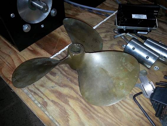
12 x 13 brass propeller
Below is one of the Harley
Davidson axle bearings and the TGP 303 Stainless shafting I'll be using in the
control through-hulls. The bearing ID is
0.750" (3/4") and the shaft is turned, ground. and polished, tempered
and quenched, at 0.7495" OD. The
fit is suh-weet!!
J

3/4" control through-hull bearing and shaft examples.
Here's a look at that Harley
bearing sitting on the TGP stainless shaft; just in case you didn't believe me
about how close the fit is. No wobble
whatsoever. Me likey!!! J

TG&P guidance control output shaft and HARLEY DAVIDSON wheel
bearing.
Tuesday, March 26, 2019: Here's the
new 7/8" drivetrain components loosely assembled
on the bench. I could not be
happier. The fit is so close that you
have to "feel for it" like inserting a HARLEY DAVIDSON wrist pin into
a connecting rod. Absolutely beautiful. 4140 - 4142 Chrome Molly; 7/8 X 36 inches;
Quenched and Tempered to a Brinell hardness between
262 and 321; precisely Turned, Ground, and Polished to minus-five
ten-thousandths of an inch. A beautiful
piece of machined stainless steel.
For this picture, the flange
bearings are situated where they will be when the tailcone
mount and propeller shaft housing are complete.
The coupler, bearings, and propeller fit the shaft with similar
precision, as well.

I'll get some Brasso or Duraglit and
polish the brass propeller like a United States Marine's belt buckle. That chrome 7/8" x 24 tpi cap nut is from a HARLEY DAVIDSON springer. It's held on with plastic tape for this
staged photo.
Next, I take the shaft to a
machinist and have him thread one inch of one end 7/8" X 24tpi; cut a
2-1/4" long 3/16" keyway in that end; a 1-1/8" keyway in the
other and it's ready to go. I gotta fab some bench mounts for
the bearings and then we can test it dry.
And when I put that aft bearing
in the side of a water tank we can wet-test the drivetrain
and prop in real time. Gimme a week.
ADNOTE: Tonight I located the shaft, bearings, propeller, and cap nut in
their general positions and held the cap nut on with a piece of plastic packing
tape. Then I installed the rudder and checked to ensure
everything fits and the clearances are just fine. I think a 12" prop is about as big as I
can run without hitting the rudder linkages but I'm sure it will be more than
adequate.

Side view of propshaft, bearings,
propeller, and cap nut in position on the actual no-shit Nautilus Minisub. J

Alternative aft view
Back in 1991, that lightened
cylindrical mount carried the lower unit of a MINN KOTA 4HP trolling
motor. (And no, it didn't put out four
horsepower and nobody can understand why Minn Kota
called it that back in the day.) It also
serves as an anchor point for the hull longerons, as
well as a structural member connecting the horizontal and vertical fins. Parts of it will be retained for structural
integrity; others removed as necessary to provide clearance when installing the
propshaft housing.
For now, this mockup of actual
parts convinces me we aren't going to have any problems with this part of the
restoration. That's a big relief when
you've been waiting for parts in the mail.
Sometimes they don't always fit like you want them to. This time, everything fits beautifully. J
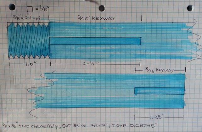
Wednesday, March 27, 2019: Here's a
simplified spec drawing I did to give the machinist an idea of what work I need
done. The threads are only
representative; I wasn't going to drive myself crazy trying to replicate 24 tpi. J
(1) Thread one end 7/8" X
24 tpi; (2) Cut a 2.25" 3/16" keyway in
that end, inboard of the threads; and
(3) cut a 1.25" 3/16" keyway in the opposite end. That's all I need.
Actually, I have the tools to
cut the keyways and thread the shaft by hand; I've done it before but it's a
lot of work on metal this hard and never as precise as what a machinist can
do. I want this to be perfect. So for this part of the job I'm farming it
out to a shop. That's a first for
me. In nineteen years, I have done every
lick of work this sub needed by hand; blacksmith style. I could do that to this shaft but that would
desecrate a beautifully-machined piece of steel and possibly put a weak link in
this vital component. No, it's
definitely machine-shop time! J
=MORE TO
FOLLOW=